2025-04-24 15:06:16
Objective: To minimize deformation in transparent thick-walled plastic parts during the injection molding process through the synergistic optimization of injection molding parameters (temperature, pressure, cooling, speed, etc.). The core principle is to balance melt flow, uniform cooling, and internal stress distribution.
I. Temperature Control: Balancing Melt Heat Dissipation and Mold Temperature
1. Barrel Temperature: Avoiding Excessive or Insufficient Heat
- Principle: Within the material's allowable melt flow index range, employ a relatively lower barrel temperature (e.g., PC: 280~300℃, PMMA: 230~250℃) to reduce melt enthalpy and subsequent shrinkage during cooling.
- Risks: Insufficient barrel temperature can lead to filling difficulties and noticeable weld lines; excessive temperature can accelerate material degradation and increase post-cooling shrinkage.
2. Mold Temperature: Enhancing Uniformity and Heat Retention
- Mold Temperature Setting: Utilizing a higher mold temperature (e.g., PC: 100~120℃, PMMA: 60~80℃) extends the melt's cooling time within the cavity, promoting molecular relaxation and reducing frozen-in stress.
- Zoned Temperature Control: Implement independent temperature control for the cavity and core, maintaining a temperature difference within ±2℃ to prevent uneven shrinkage caused by localized overheating or overcooling.
- Cooling Medium: Employing an oil temperature controller instead of water cooling provides more precise temperature control (fluctuation ≤±1℃), which is particularly beneficial for the slow cooling requirements of thick-walled parts.
II. Pressure and Speed: Suppressing Internal Stress Generation
1. Injection Pressure: Segmented Control to Avoid Excessive Clamping Force
- Multi-Stage Pressure Setting:
- Filling Stage: Use a medium-low injection pressure (60~80MPa) and a slower injection speed (20~30mm/s) to minimize melt shear heating and molecular orientation.
- Holding Stage: Implement a stepped holding pressure profile (e.g., first stage at 80% of peak pressure for 5~10 seconds; second stage at 50% of peak pressure until gate freeze-off), with the total holding time accounting for 25%~35% of the entire injection cycle.
- Back Pressure: Applying a lower back pressure (3~5MPa) reduces shear stress on the melt during screw rotation, preventing material degradation.
2. Holding Pressure and Time: Precisely Matching Cooling Rate
- Pressure Decay: Monitor in real-time using pressure sensors and immediately cease holding pressure when the melt at the gate freezes (indicated by a sharp drop in the pressure curve) to prevent over-packing and the generation of reverse stress within the part.
- Case Study: For thick-walled PC parts (wall thickness ≥5mm), the holding time can be extended to 20~30 seconds, but this requires a corresponding increase in mold temperature (e.g., 110℃) to prevent premature surface solidification and subsequent internal shrinkage.
III. Cooling System: Enhancing Uniformity and Efficiency
1. Cooling Channel Design Optimization
- Structure: Employ spiral cooling channels surrounding the cavity or a combination structure of baffles and bubblers to ensure adequate cooling in thick-walled regions (such as ribs and bosses).
- Flow Rate and Temperature: The cooling medium flow rate should be ≥1.5m/s, and the inlet temperature should be 10~15℃ lower than the mold temperature (e.g., if the mold temperature is 100℃, set the oil temperature to 85℃) to avoid excessive temperature gradients that can lead to rapid surface cooling.
2. Cooling Time: Calculation Based on Solidified Layer Thickness
- Formula Estimation: tc = 2/(pi^2 alpha) h^2 ln(8/(pi^2) Delta T/) (where h is the part thickness, alpha is the material's thermal diffusivity, and Delta T is the allowable temperature difference).
- Objective: Ensure that the core temperature of the part is close to the material's heat deflection temperature (e.g., PC ≥130℃) at the time of ejection, and that the temperature difference between the surface and the core is ≤15℃, to minimize post-ejection shrinkage and deformation.
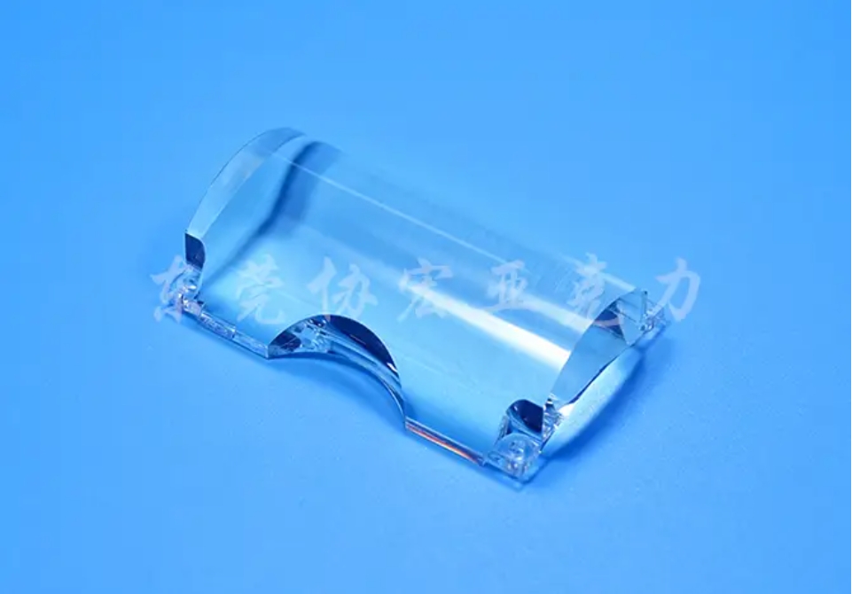
IV. Synergistic Adjustment of Other Process Parameters
1. Injection Speed: Employing Low-Speed Filling to Reduce Molecular Orientation
- Segmented Speed Control:
- Initial Filling Stage: Use a low injection speed (15~25mm/s) for smooth advancement of the melt, preventing jetting.
- Later Filling Stage: Further reduce the injection speed (10~15mm/s), and employ a "micro-speed" (5mm/s) when approaching full cavity fill to minimize impact pressure.
- Risk Warning: Excessively slow injection speed can lead to premature melt cooling, requiring a corresponding increase in barrel and mold temperatures.
2. Ejection Design: Reducing Ejection Resistance
- Ejector Pin Layout: Increase the number of ejector pins in thick-walled areas (spacing ≤30mm) and use larger diameter ejector pins (diameter ≥4mm) or a stripper plate for ejection to avoid localized stress concentration.
- Draft Angle: For transparent parts, the draft angle should be ≥1.5°; for thick-walled parts, it can be increased to 2°~3° to reduce friction during ejection.
3. Post-Processing: Annealing to Relieve Residual Stress
- Process: Place the molded parts in an oven at a temperature 10~20℃ above the material's glass transition temperature (Tg) for a specific duration (e.g., PC at 120℃ for 2 hours), followed by slow cooling to room temperature within the oven.
- Effect: This allows the frozen molecular chains within the part to further relax, reducing internal stress (which can be detected by a polarized light stress analyzer, showing a significant reduction in stress fringes).
V. Typical Defects and Process Adjustment Comparison Table
(A table listing common defects in transparent thick-walled plastic parts and their corresponding process adjustment recommendations should be included here, but specific table content was not provided.)
Copyright Xiehong Plastic Mold and Manufacturing Tech Co., Ltd. All rights reserved.
